
Product Description
1.1 Product Description
Place of Origin: | Changsha, Hunan |
Company Name | Willfar Information Technology Co., Ltd. |
Certification: | CNAS CMA |
Model Number: | WFDT-7000R |
Minimum Order Quantity : | 100 |
Packaging Details : | Carton Packaging |
Delivery Time : | 30 days |
Payment Terms : | T/T |
Supply Ability : | 200 per day (based on the number of the order) |
1.2 Detail Information
Color: | Grey | Brand: | Willfar Information |
Operating Humidity | 10% ~ 98% | Working Temp.: | -40~+70℃ |
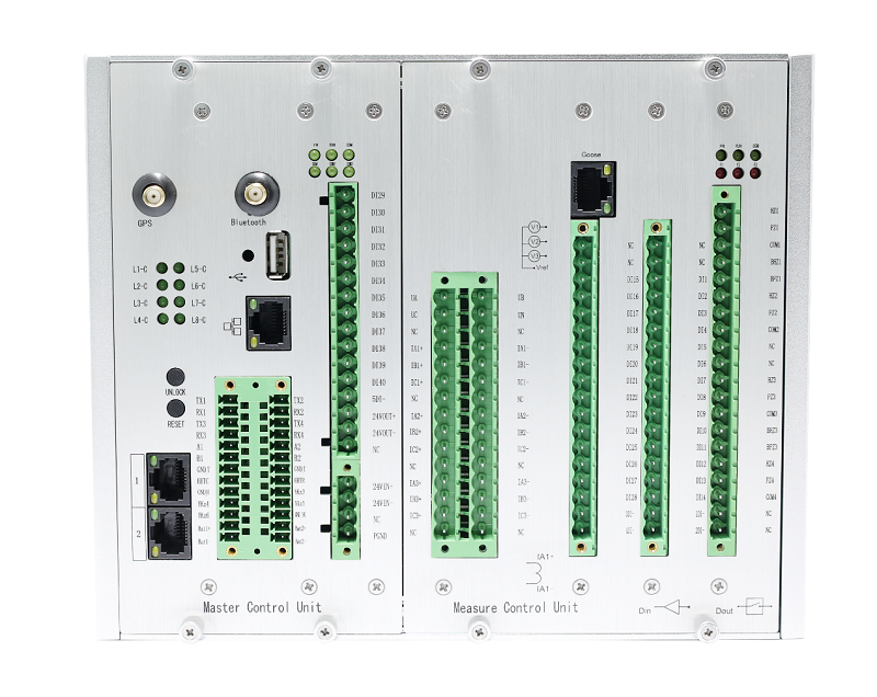
Weight | ≤4400g | Dimension: | 257mm×177mm×150mm (W×H×D) |
Highlight: | remote control remote data concentrator | ||
1.3 Overview
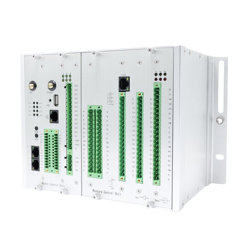
The WFDT-7000R Remote Terminal Unit (RTU) is designed for installation in secondary rooms of ring network cabinets, distribution rooms, and switchgear cabinets. It employs a 32-bit embedded software and hardware platform, a professional embedded operating system, and adheres to rigorous industrial design principles among other advanced technologies. This unit is adept at supervising integrated systems for distribution automation including ring main units, distribution rooms, and compact substations. It features an extensive library of communication protocols, supporting a wide array of international standards and protocols such as 101/104/IEC61850, enabling seamless interaction with various intelligent distribution devices. The WFDT-7000R is equipped with comprehensive capabilities for managing both remote and local operations of switches. It facilitates a network-type, locally distributed functionality through direct, device-to-device communication, enabling swift fault detection, isolation, and expedited power restoration. This significantly reduces the time needed for fault isolation and power resumption to milliseconds, while minimally affecting non-fault areas with self-healing times reduced to seconds. All interfaces comply with IEEE and IEC standards, showcasing the unit's remarkable functionality, ease of use, stable performance, straightforward maintenance, reliable operation, exceptional openness, and superior cost-effectiveness.
1.4 Key Parameters
NO. | Item | Technical Parameter |
1 | Operating voltage and range | DC24V±20% |
2 | Operating frequency | 50Hz/60Hz |
3 | Power consumption | <15W |
< 0.5VA/phase AC voltage loop | ||
< 0.75VA/phase AC current loop | ||
4 | Opening and closing operating voltage | DC 220V /110V /48V/24V (Optional) |
5 | Capacity of digital output | DC24V/10A |
6 | AC rated current | ECT:225mV |
7 | AC rated voltage | EVT: 3.25/√3 |
8 | Overload capacity of current loop | 2In continuous work;10In/10s;20In/1s |
9 | Overload capacity of voltage loop | 1.2Un,continuous work |
10 | Measurement accuracy | ≤0.5% Voltage and Current |
11 | Protect accuracy | 3P |
12 | SOE resolution | ≤2ms |
13 | Accuracy of time stamping for remote signal inputs | ≤1ms |
14 | DC voltage range | DC:0V~30V |
15 | Number of voltage input | 3 |
16 | Number of current input | 9 |
17 | Number of digital output | 4(operated for a preset time 0.1s to 6s) |
18 | Number of digital input | 40(time-stamped 1ms accuracy) |
19 | Number of Ethernet | 2(10M/100M) |
20 | Number of RS232 | 4 |
21 | Number of RS485 | 2 |
22 | Timing mode | Synchronization succeeded in 3 seconds. |
1.5 Features
(1) The terminal collects and calculates the effective values of phase voltage, line voltage, zero sequence voltage and current, and calculates electrical quantities such as active power, reactive power, power factor and frequency. And it can upload the measurement data to Head-End System.
(2) The terminal has the function of setting the dead zone of telemetering value change, and when the measured value changes beyond the dead zone, the value is sent. It has a dead zone setting for telemetry value to return to zero, which is zero when the measured value is within the dead zone.
(1) Query the basic information of the terminal, including the version number of hardware and software, check code, etc.
(2) It has the self-check function, and the self-check information includes abnormal signal of the device, abnormal communication, etc. The self-check information can be browsed and uploaded.
(3) Query the telemetry and telecommunication data of each interval.
(4) Control each interval.
(5) Inquire and set the parameters of the terminal locally and remotely.
(6) Real-time monitoring device internal diagnostic data and records.
(7) The software can automatically return to normal when it is abnormal.
(1)Support the cyclic storage of at least 64 groups of recorded data and upload them to the main station.
(2)The starting conditions of wave recording function include over-current fault, line voltage loss, zero-sequence voltage and zero-sequence current mutation, etc. The parameters of starting conditions can be set remotely and locally.
(3)The wave recording content should include waveform data of not less than 4 cycles before the fault occurs and not less than 8 cycles after the fault occurs, and the number of wave recording points should be not less than 80 points/cycle, and the wave recording data should include voltage, current, switch position, etc. It is necessary to meet the wave recording of at least 2 circuits.
(4)The wave recording adopts file transmission mode, and the wave recording file format follows the format defined in Comtrade 1999 standard, and only two files, CFG (configuration file, asc11 text) and DAT (data file, binary format), are used.