Product Description
Place of Origin: | Changsha, Hunan |
Brand Name: | Willfar Information Technology Co., Ltd. |
Certification: | CNAS |
Model Number: | WFDT-7000R |
Minimum Order Quantity : | 100 |
Packaging Details : | Carton Packaging |
Delivery Time : | 30 days |
Payment Terms : | T/T |
Supply Ability : | 200 per day (based on the number of the order) |
Detail Information
Color: | Grey | Brand: | Willfar |
Operating Humidity | 10% ~ 98% | Working Temp.: | -40~+70℃ |
Weight | ≤4400g | Dimension: | 257mm×177mm×150mm (W×H×D) |
High Light: | remote control remote data concentrator | ||
Product Description
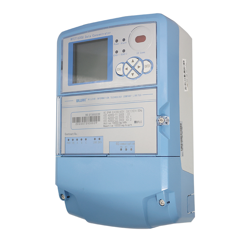
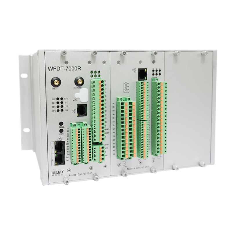
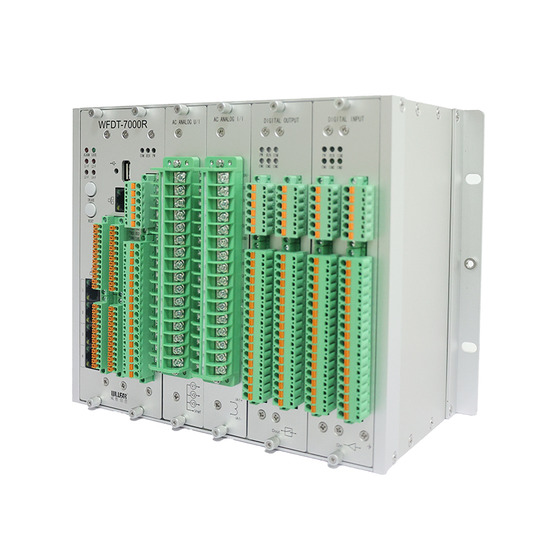
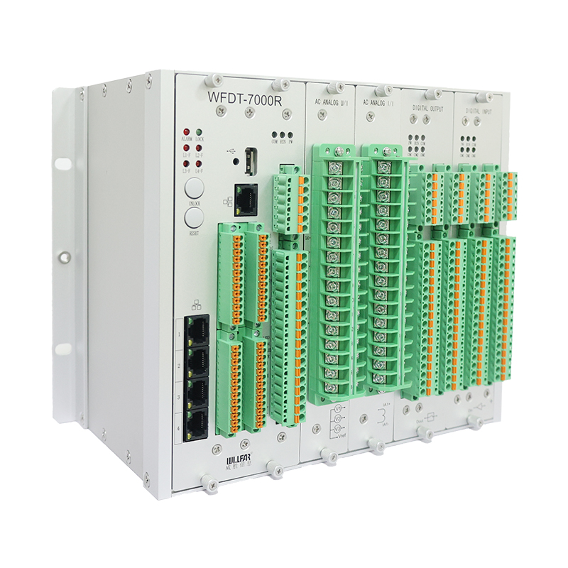
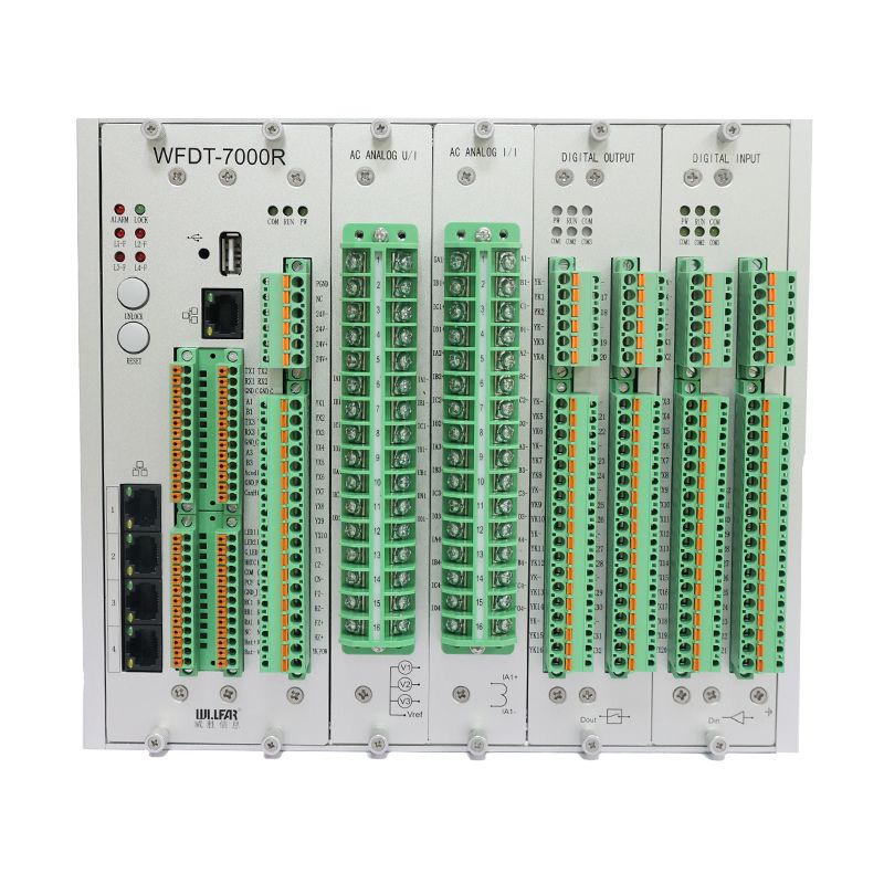
l WFDT-7000RRemoteTerminalUnit(RTU) is a kind of power distribution monitoring terminal which follows IEC international standards, adopts the most advanced power monitoring technology, has good real-time, reliability and interoperability, and is suitable for comprehensive and real-time monitoring and control of primary and secondary equipment in ring network cabinets, power distribution rooms and substations.
l WFDT-7000RRemoteTerminalUnit(RTU) is installed in the secondary room of ring network cabinet, distribution room and switch cabinet, and adopts 32-bit embedded software and hardware platform, professional embedded operating system, strict industrial design and other technologies. It can cover distribution automation integrated systems such as ring cabinets, distribution rooms, box-type substations, etc. It has a rich library of communication protocols, supports various international standards and protocols including 101/104/IEC61850, and can communicate with various intelligent distribution devices. All interfaces meet IEEE and IEC standards, and it has the characteristics of powerful functions, simple use, stable operation, convenient maintenance, reliable performance, good openness and high cost performance.
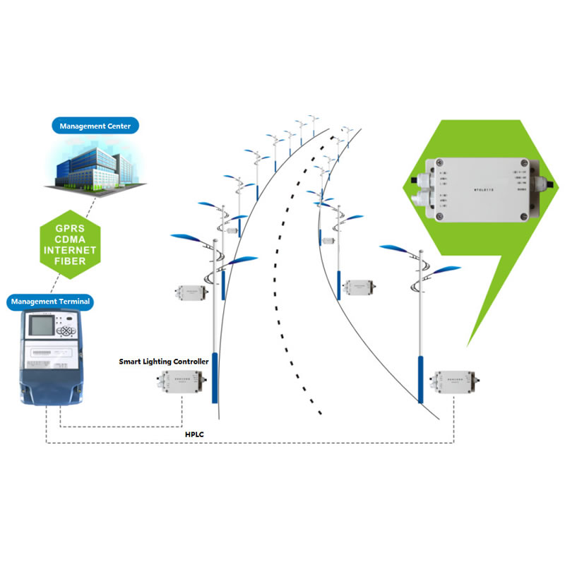
l WFDT-7000RRemoteTerminalUnit(RTU)is an integrated automatic outdoor monitoring and control terminal integrating line protection, control, measurement and signal monitoring. It has all the functions of handling the remote/local operation of switches, meets the network-type local distributed function through peer-to-peer communication between devices, and realizes rapid fault location, fault isolation and rapid power supply recovery, which obviously shortens the time of fault isolation and power supply recovery, shortens the time of fault isolation to millisecond level, and shortens the self-healing time of non-fault areas to second level.
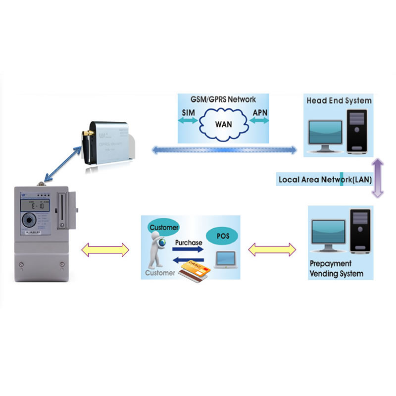
l In additional, RTU also has the function of collecting environmental data of transformer room, oil temperature data of transformer and related data of electrical equipment at low voltage side of transformer.
Technical Parameters
S.N. | Name | Specified | Description |
1 | Operating Voltage | AC 220V | ±20% fluctuation |
DC24V | ±10%(external configuration of AC220V power module is required) | ||
2 | Power consumption | ≤15W | |
< 0.5VA/phase | ac voltage loop | ||
< 0.75VA/phase | accurrentloop | ||
3 | Opening and closing operating voltage | Optional | DC 220V /110V /48V/24V AC 220V /110V |
4 | Capacity of DigitalOutput | DC24V/16A AC220V/16A | |
5 | AC Rated current | CT:5A/1A ECT:225mV | |
6 | AC Rated voltage | VT:220V/100V EVT:3.25V | |
7 | Frequency | 50Hz/60Hz | |
8 | Overload capacity of current loop | 20In | 2Incontinuous work;10In/10s;20In/1s |
9 | Overload capacity ofvoltageloop | 2Un | 1.2Un,continuous work |
10 | Measurement accuracy | ≤0.5% | Voltage and Current |
11 | Protect accuracy | ≤3% | |
12 | SOE resolution | ≤2ms | |
13 | Accuracy ofdigitalinput time tag | ≤1ms | |
14 | DC voltage measure range | DC:0V~60V | |
15 | Number of voltage input | 3 | |
16 | Number of current input | 9 | |
17 | Number of digital output | 4 | operated for a preset time0.1s to 6s |
18 | Number of digital input | 40 | time-stamped 1ms accuracy |
19 | Number of Ethernet | 2 | 10M/100M |
20 | Number of RS232 | 4 | |
21 | Number of RS485 | 2 | |
22 | Timing mode | SCADAorIRIG-B | Synchronization succeeded in 3 seconds. |
23 | Size | 257×177×150mm | (W×H×D) |
Features
Electrical measurement
(1) The terminal collects and calculates the effective values of phase voltage, line voltage, zero sequence voltage and current, and calculates electrical quantities such as active power, reactive power, power factor and frequency. And can upload the measurement data to the master station.
(2) The terminal has the function of setting the dead zone of telemetering value change, and when the measured value changes beyond the dead zone, the value is sent. It has a dead zone setting for telemetry value to return to zero, which is zero when the measured value is within the dead zone.
Running state monitoring
(1) Query the basic information of the terminal, including the version number of hardware and software, check code, etc.
(2) It has the self-check function, and the self-check information includes abnormal signal of the device, abnormal communication, etc. The self-check information can be browsed and uploaded.
(3) Query the telemetry and telecommunication data of each interval.
(4) Control each interval.
(5) Inquire and set the parameters of the terminal locally and remotely.
(6) Real-time monitoring device internal diagnostic data and records.
(7) The software can automatically return to normal when it is abnormal.
Waveform Recording
(1)Support the cyclic storage of at least 64 groups of recorded data and upload them to the main station.
(2)The starting conditions of wave recording function include over-current fault, line voltage loss, zero-sequence voltage and zero-sequence current mutation, etc. The parameters of starting conditions can be set remotely and locally.
(3)The wave recording content should include waveform data of not less than 4 cycles before the fault occurs and not less than 8 cycles after the fault occurs, and the number of wave recording points should be not less than 80 points/cycle, and the wave recording data should include voltage, current, switch position, etc. It is necessary to meet the wave recording of at least 2 circuits.
(4)The wave recording adopts file transmission mode, and the wave recording file format follows the format defined in Comtrade 1999 standard, and only two files, CFG (configuration file, asc11 text) and DAT (data file, binary format), are used.